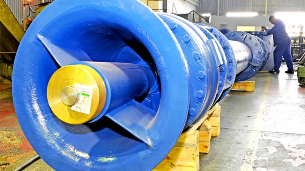
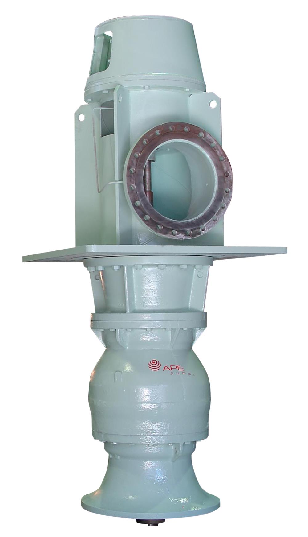
Vertical Industrial Turbine Pumps
Applications
The pumps can be used in any industrial or agricultural application.
They can be used in:
- Steel works
- Chemical process plants
- Effluent Disposal
- Cooling Water Circulation
- Irrigation
- Water Works and Raw Water Supply
- Shaft Sinking and Dewatering
- Pipeline Booster and Transfer Service
- Condensate Extraction
Features
- Civil work is easier and cheaper.
- Installation is easier.
- There is no suction valve with consequent cost and pressure loss savings.
- Efficiencies are as good as any.
- NPSH probles are eliminated.
- Space is saved and by using weather proof motors, there is no necessity for a building to be erected.
- There is no danger of flooding the electrics.
- By adding stages, a very wide range of duties can be covered with standard parts, thus making for cheap and readily available spares.
- The pumps have generally a non-overloading KW characteristic, and a steep head quantity curve.
- There are no radical loads on the bearings or glands, so they last longer and maintenance is reduced.
- In dirty water, grit tends to fall vertically out of the wear areas and so does less damage.
Specifications
The pump materials and assembly are selected from a number of standard variations to suit the particular application.
The casings are generally made in a high quality close-grained cast irion and have long radius water passages to give the best performance in terms of efficiency and life. Casings in bronze and stainless steel are also available.
The impllers are of mixed flow design and can be either open-vane or shrouded, depending on the size. The shrouded impellers have long suction eye rings, to give good life and performance. They are usually fitted to the shaft by means of a taper sleeve, using a key when the load requires it.
The shaft is of stainless steel, running in bearings chosen to suit the application. These include fluted cutless rubber, asbestos compounds and bronze. They can be product-lubricated or pressure-fed grease-lubricated.
The column pipe is either screwed or flanged steel suitably protected for the application. The bearing spiders are so high grade cast iron and the bearing brushes are as used in the pump. The line shafting can be product-lubricated or enclosed in a cover tube with oil, water or grease-lubricated.
The discharge head is either a rigid cast iron or fabricated steel bend with spigotted seats for the thrust bearing and drive motor stool. It contains the housing for the stuffing box.
Soft packed glands, mechanical seals, or a glandless arrangement can be offered.
Versatility of installation
The pumps are designed for any type of drive:
- Electric Motor
- Belt Drive
- Gear Drive
- Engine or Steam Turbine
They can be suspended in wet sumps, boreholes, rivers, steel tanks or dams; in dry pits with a suction pipe connected to the bellmouth or as a "pot" pump with various positions of the inlet and outlet branches.
Sections and Parts
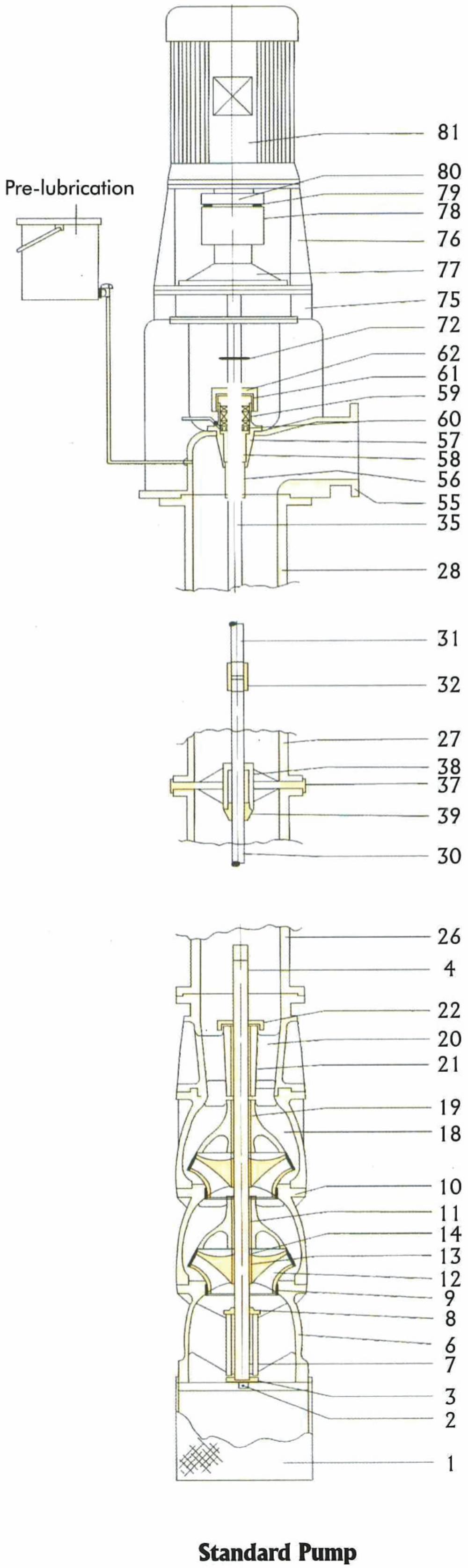
Discharge Head
81 Motor
80 Motor Half Coupling
79 Coupling Pins and Rubbers
78 Pump Half Coupling
77 Thrust Assembly
76 Motor Stool
75 Adaptor Stool
71 Grease or Water Line
70 Drip Feed Lubricator
69a Stuffing Box (relief type)
69 Cover Tube Stuffing Box
68 Cover Tube Top Cover Seal
67 Cover Tube Top Cover Bush
66 Cover Tube Top Cover
65 Tension Tube Cap
64 Tension Tube Locknut
63 Tension Tube Nut
62 Stuffling Box Cap
61 Gland
60 Lantern Rings
59 Gland Packing
58a S/B Bush (pressure system)
58 Stuffing Box Bush
57 Stuffing Box
56 Stuffing Tube
55 Discharge Head
Column Assembly
52 Cover tube circlip
51 Headshaft coupling key
50 Tension Tube
49 Covertube "O"-ring
48a Top C/tube ("O"-ring type)
48 Top C/Tube (for screwed col)
47a Interm C/tube ("O"-ring type)
47 Interm C/tube (for screwed column)
46a Bottom C/tube ("O"-ring type)
46 Bottom C/tube (for screwed column)
45 Convertible Connector Bearing
44 Column Spacer
43 Column Socket
42 Covertube Spider Bearing
41a Covertube Spider (screwed column)
41 Covertube Spider (flanged column)
40 Bearing Retainer Circlip
39 Bearing Retainer Cap
38 Bearing Retainer Bush
37b Brg Ret. (for screwed column)
37a Brg. Ret (for grease lub or water flush)
37 Bearing Retainer (flanged cols)
35 Head Shaft
34 Coupling Spacer
33 Ringer Feeder Locking Ring
32a Lineshaft Coupling (ring-feeder)
32 Lineshaft Coupling (screwed type)
31 Intermediate Lineshaft
30 Bottom Lineshaft
29 Connector Flange
28 Top Column
27 Intermediate Column
26 Bottom Column
Bowl Assembly
23a Top Connector Bearing ("O"-ring type)
23 Top Connector Bearing
22 Top Sand Slinger
21 Top-section Bush
20a Top-section (oil lub)
20 Top Section (water lub)
19 Top-Mid Section (bush)
18a Top-mid Section (screwed)
18 Top-mid Section (flanged)
17 Black Eye Ring Plate
16 Black Eye Ring
15 Pump Shaft Key
14 Impellar Taper Sleeve Lock Nutt
13 Impeller Taper Sleeve
12b Closed Impeller (back eye ring type)
12a Open Impeller
12 Closed Impeller
11 Middle Section Bush
10a Middle Section (screwed)
10 Middle Section (flanged)
9 Bottom Section Wear Ring
8 Bottom Sand Slinger
7 Bottom Section Bush
6a Bottom Section (screwed)
6 Bottom Section (flanged)
5 Sump
4 Pump Shaft
3 Upthrust Collar
2 Upthrust Collar Bolt
1a Borehole Strainer
1 Basket Strainer
Typical Installations:
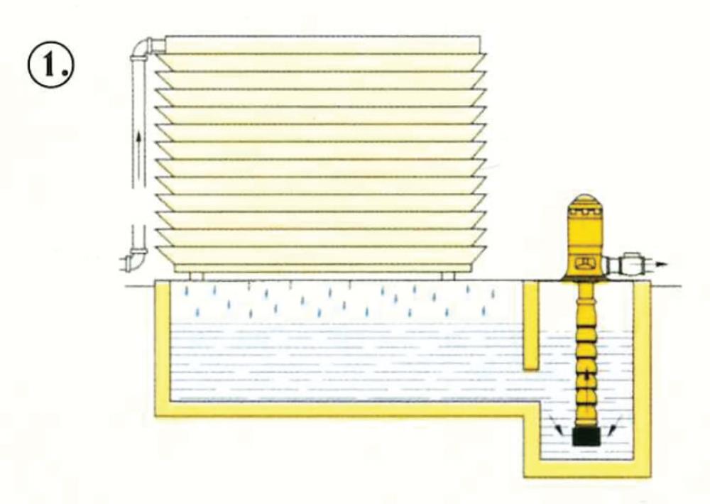
1. Cooling Tower Recirculation
Eliminates priming problems; multi-staged to suit pressure requirements.

2. Raw Water
The pot pump is ideal for raw water intake, and simplifies structures.

3. Primary Fueling Service
Volatile fluids require submerged pump units
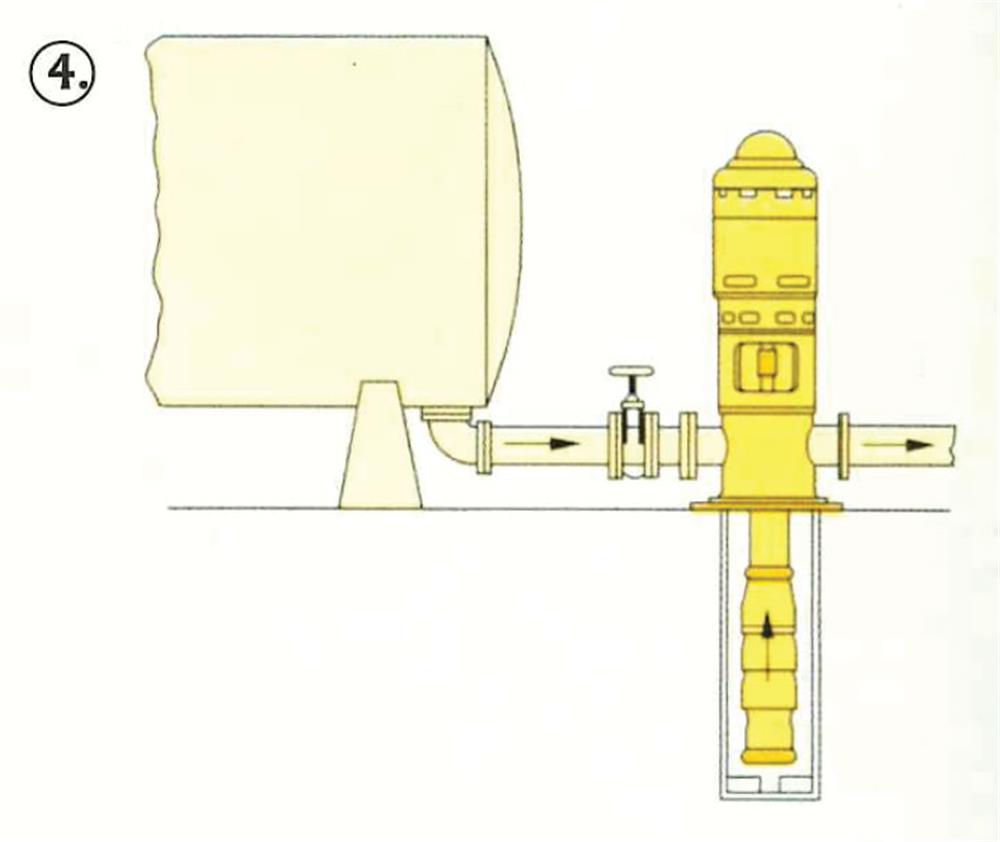
4. Transfer Service
Self contained unit is ideal for L.P. gas transfer
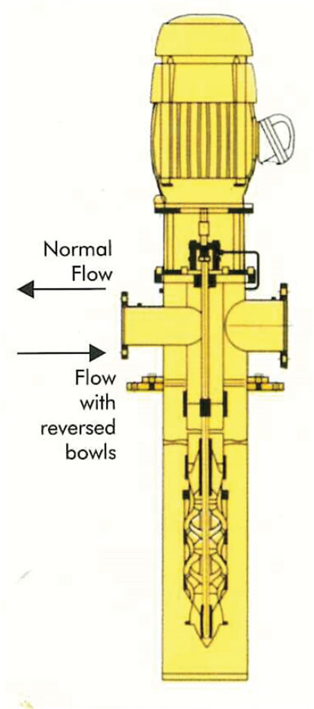
As a "Pot" Pump:
The "pot" pump is particularly useful for inline boosting. It requires no priming and to a limited extent is self priming. It conserves space and requires minimum civil work and operational maintenance.
By reversing the pump bowls, the flow direction is reversed and low pressure glands result, even in very high pressure boosting applications.
in other applications it can be made completel glandless.
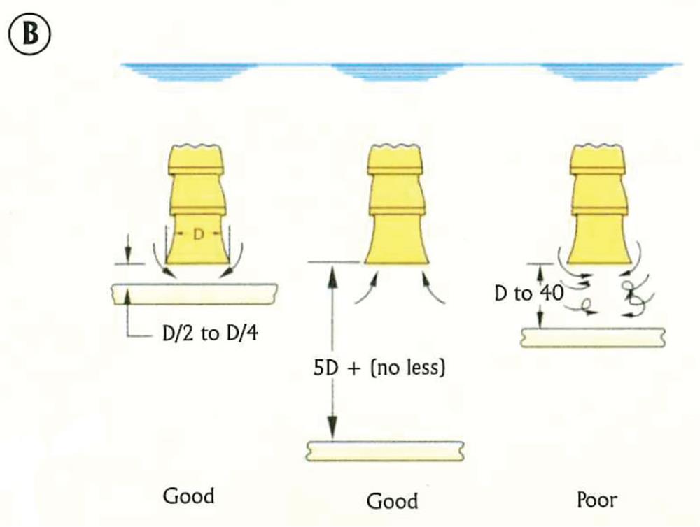
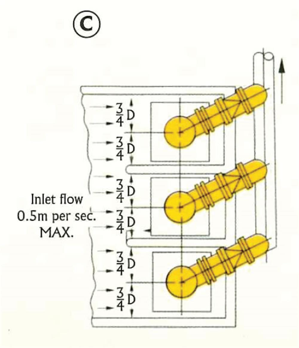
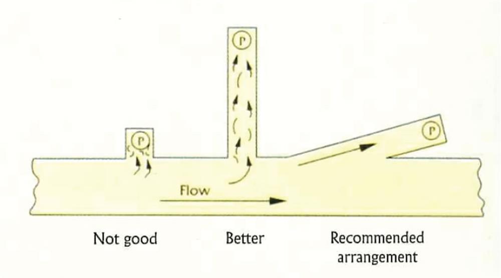
Sump Design
These sketches show some established criteria for proper sump design. These include submergence, clearance from the floor and walls, spacing between the units when more than one pump is involved, and flow distribution and velocities.

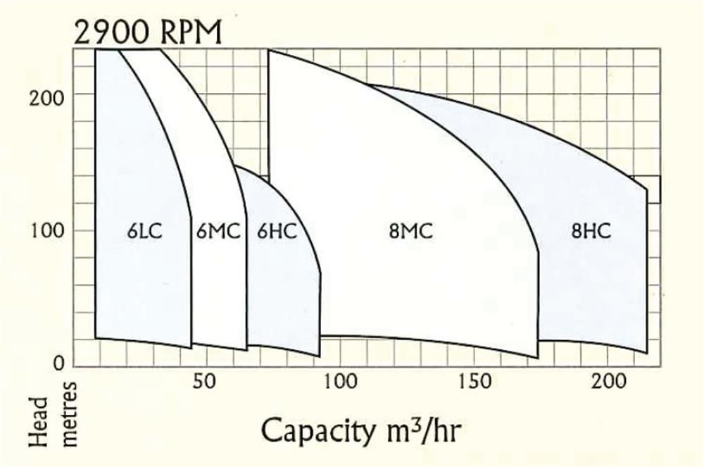
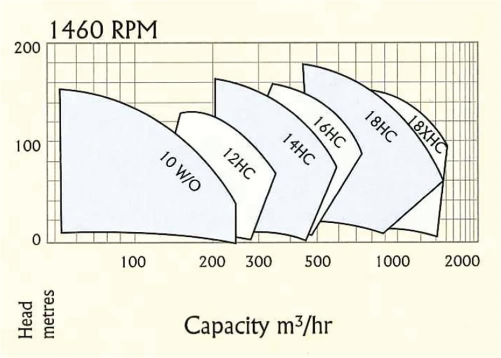
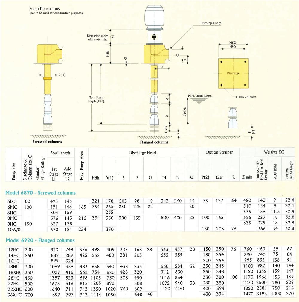
Pump Dimensions
Pump Performance